Topic 4
Introduction to Analysis and Design: Domain models, Use cases
What we will cover this week
- What is Analysis and Design?
- What is UML?
- Domain Models and Class Diagrams
- Use Case Diagrams
Introduction to analysis and design
What is Analysis and Design?
When building software, we need to ensure we create something which is what the user wants. To achieve this, we should perform analysis and design before we start coding. There are two components:
- Analysis: We analyse the problem by breaking it down to get an idea of such things as:
- How a user will interact with the system
- How the system will respond
- How the system will react to errors
- Design: using our analysis, we design the classes in our system by working out their attributes and methods and how they interact
UML: Unified Modelling Language
Object-oriented analysis and design makes use of UML. UML is an extensive set of diagrammatic tools to enable developers to analyse a problem and design an object-oriented solution to the problem before coding it. These diagrammatic tools include (but are not restricted to):
- Use-case diagrams
- Class diagrams
- Sequence diagrams
UML is not an analysis and design process; rather it is a set of tools which can aid us in that process. It can be used in various different analysis and design techniques, such as ICONIX.
The problem statement
Analysis and design starts with a problem statement. This is a written description of what is required of the application, and will typically be produced by gathering requirements from the target users. Here is an example:
What do we do with the problem statement?
We perform an analysis on the problem statement and derive two classes of artefact from it:
- The domain model and initial class diagrams. These represent potential classes in the system and how they interact. Thus, we are thinking of the system from a code-oriented point of view.
- The use case diagram. This is a diagram showing how users can interact with the system and what tasks different types of user can perform. Thus it is thinking of the system from a user-oriented point of view.
The domain model
The domain model is an initial diagram showing possible classes in the system, and their interaction. We derive it by:
- analysing the problem statement, and looking for nouns (e.g. person, cat, computer, etc) and their interactions - these are our first guess at classes in the system
- Having derived a list of possible objects, we then connect them together to illustrate the relationship between them
Exercise 1
Answer to exercise 1
For the student records application, specified in the problem statement above, we could identify likely nouns as below:
- university;
- student (including undergraduate and masters; this could be an inheritance relationship);
- module.
We also possibly have:
- unique ID;
- name;
- thesis topic.
but these are just simple items of data which could be represented as numbers and strings and therefore do not need their own classes. Furthermore we also have:
- university administrator,
but this is a bit different. The administrator will be a user of the software (an actor - see discussion on use cases below), not an entity that the software needs to manage. We consider users later, when doing use cases. So from this analysis we could derive a domain model as below:
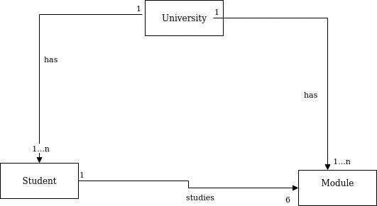
This shows the three possible classes in the system, and the relationship between them as annotations.
Multiplicity
The domain model also includes multiplicity. Multiplicity is an indication of how many objects of each class are interacting with each other. The diagram above is indicating that:
- A University may contain one or more (
1..n) Modules. This is known as a one-to-many relationship. - A University may contain one or more (
1..n) Students - A Student studies 6 Modules (shown as simply
6) - We could also have a one-to-one relationship potentially, where one class contains just one instance of another class. This would be shown by the multiplicity
1.
Class diagrams
Class diagrams show the classes in the system, their inter-relationships, and the attributes and methods of each class. The class diagram is an extension of the domain model, with attributes and methods added.
How to derive the class diagram
- Classes and their interrelationships come from the domain model
- When first analysing the problem statement, you can add a first guess at likely attributes to the domain model to produce an initial class diagram
Class diagram syntax
Each class is represented by a box, with content as follows:
- Each class begins with the class name, followed by a horizontal line
Attributes are denoted by:
where ACCESS is:
- + : public - accessible from anywhere
- - : private - accessible only from instances of the current class
- # : protected - accessible from instances of both the current class and subclasses
- A further horizontal line separates the attributes and methods
Methods also have an access indicator, and show parameters and return types are, using this syntax (also used in the Kotlin language, which many of you will do next term):
- Regular lines, annotated by multiplicity indicators, link classes (as in the domain model)
- Additionally, arrows with unfilled heads indicate inheritance
- There are also special syntaxes for aggregation and composition
Here is an example, based on the domain model above. Note that for now, we have only added attributes. Methods are typically added later in the analysis and design process, as we saw above. I have just added one method to show the syntax.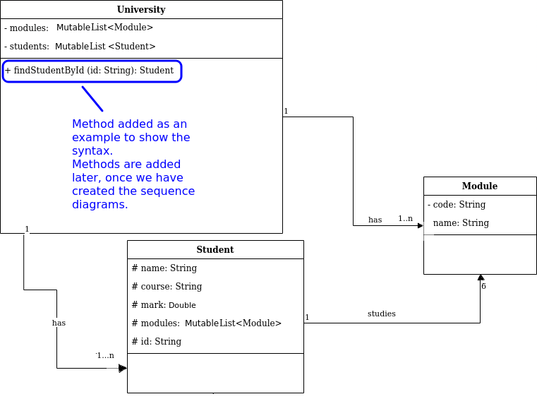
Note that many the attributes we have added can be derived from the problem statement, above. Also, where a class contains one or more of another (e.g. a university contains one or more students or modules) this would translate to an attribute representing a collection of data, such as a list. So a one-to-many relationship (1..n) would require a list of the entity at the "many" end of the relationship, and a one-to-one relationship (1..1) would require a simple attribute. For example, the University contains one or more Students so the University would need to contain a MutableList of Student objects. Specifically it would be a MutableList because we need to be able to add new students to it when enrolling students.
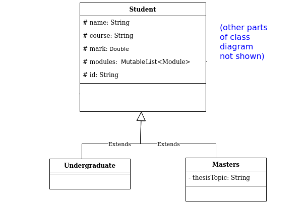
Inheritance in class diagrams
Inheritance in class diagrams is shown via an open arrow pointing at the superclass, for example: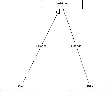
We could extend our university system class diagram by showing Undergraduate and Masters students inheriting from Student.
Use cases
The other step we need to take as an initial analysis and design step is use-case analysis. This takes a different approach to the problem compared to the domain model by considering the system from a user point of view; i.e. thinking about how the user will interact with the system. For example, we consider questions such as:
- Who are the users?
- How are they able to interact with the system?
After performing use-case analysis, we produce a use-case diagram and then (ideally) use-case texts.
An example use case diagram
A use case diagram shows:
- The actor(s)
- These are the external entities interacting with the system: typically, but not necessarily, humans (the university administrator in our example)
- Actors can be non-human, for example if an automated background process was interacting with the system (e.g. auto-removing students whose degree has finished) this would be an actor too
- Represented by matchstick figures
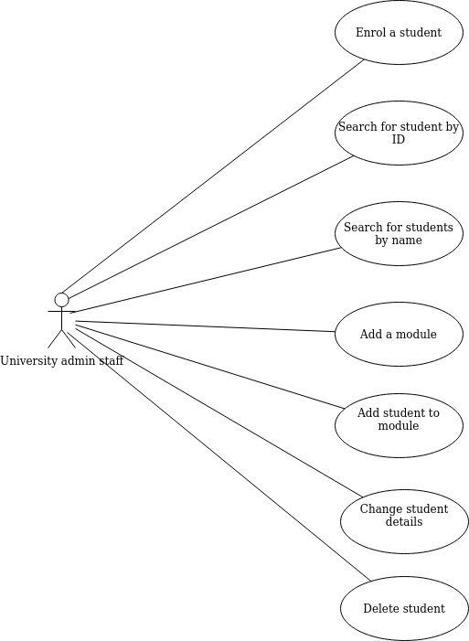
- The use cases themselves
- These are the tasks which the actors need to perform with the system
- They can be derived by analysing the problem statement
- e.g. for the university admin application, these could be:
- Enrol student
- Search for student by ID
- Search for students by name
- Create module
- Add module to student
- Edit student details
- Delete student
- From these, we would draw the use-case diagram below. Note the actor (matchstick figure) and use cases themselves (shown as ovals).
Dependencies between use cases
A more detailed use-case diagram will show dependencies between use cases. Dependencies include:
- A use case extending another; this is when the second use case is an optional extension of the first
- For example,
delete a studentmight extendsearch for a student, because after searching for a student object, the administrator might optionally delete it
- For example,
- A use case including another; this is where the second use case is part of the process of the first
- For example,
enrol a studentmight includeedit student details, because student details is part of the process of enrolling a student
- For example,
- A use case preceding another; this indicates that the first use case must take place sometime before the second
- For example, the
loginuse case might precede enrolling a student, updating a student's details, or deleting a student
- For example, the
An example is here: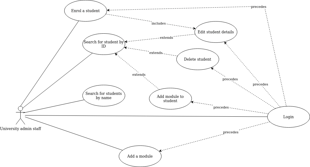
See draw.io: "Draw a UML use case diagram".
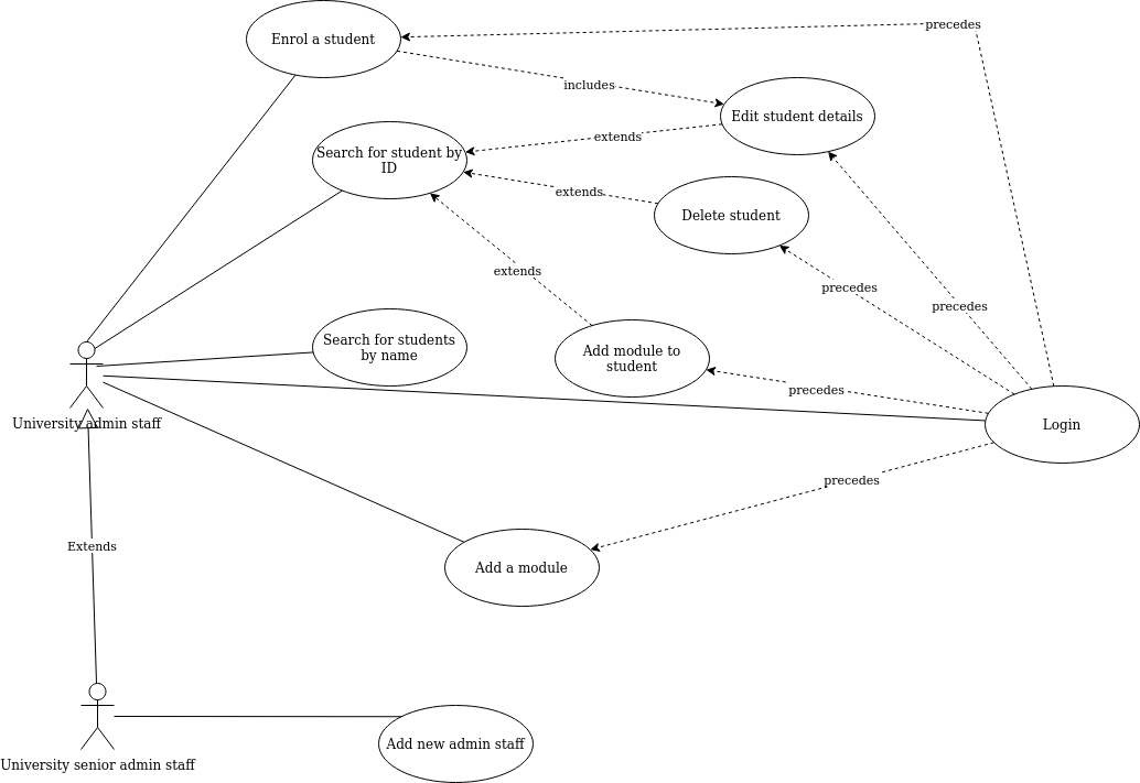
Generalised and specialised actors
- A use-case diagram can have more than one actor, as different use cases might be performed by different actors
- Through use of the generalisation symbol in UML (an arrow with an unfilled arrow-head), we can distinguish between generalised actors and more specialised actors
- An example for the university system might be if senior administrators (only) were allowed to add staff. The senior administrator is a more specialised version of the administrator, so they can do all use cases that administrators can do, as well as their own specific use case of adding a member of staff.
- The example below shows this
Drawing the diagrams - draw.io
We will be using draw.io, an online piece of free software, to draw the diagrams. The labs will start with a live demo of this so please ensure you attend (or if you cannot attend, please ensure you watch the video later). draw.io have produced a very useful and extensive blog explaining how to draw different types of diagram. You will probably find the following particularly useful:
Exercise 2
Answer to exercise 2
By analysing the nouns, we could come up with:
- Venue (to manage the venue as a whole)
- Event (representing a single event)
- Booking (representing an individual booking)
- Customer. Note that even though a customer is potentially an actor, being a user of the system, they would also need to be modelled by the software. It is stated in the problem statement that customers should be able to manage bookings, therefore the software needs to represent a
Customerin code. Thus, it makes sense to have aCustomerclass which containsBookingobjects. - By contrast we do not need a
Staffclass. TheStaffare purely users of the system, i.e. actors.
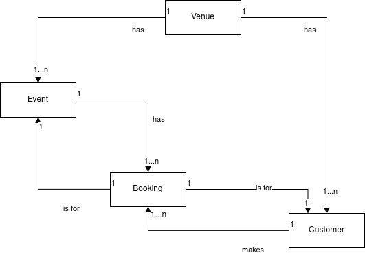
In terms of relationships, we should be able to work out that:
- One
Venuecontains many events; - One
Eventcontains manyBookings (this is needed to cancel all bookings for an event) - One
Bookingreferences oneEvent(when we view a booking, we need to see the event details - so we need a two-way relationship here); - One
Venuecontains manyCustomers; - One
Customercontains manyBookings (the customer needs to be able to view and cancel all their bookings) - No direct relationship between
VenueandBookingis needed: according to the problem statement, all interaction with bookings goes via the event or the customer. - (For the more advanced requirement)
Bookingshould contain a reference toCustomer. This is because when cancelling all bookings for an event, the customers who made the bookings need to be informed, and the easiest way to enable this is to store a reference to theCustomerin eachBooking.
Exercise 3
Answer to exercise 3
This is shown on the domain model below.
Exercise 4
Answer to exercise 4
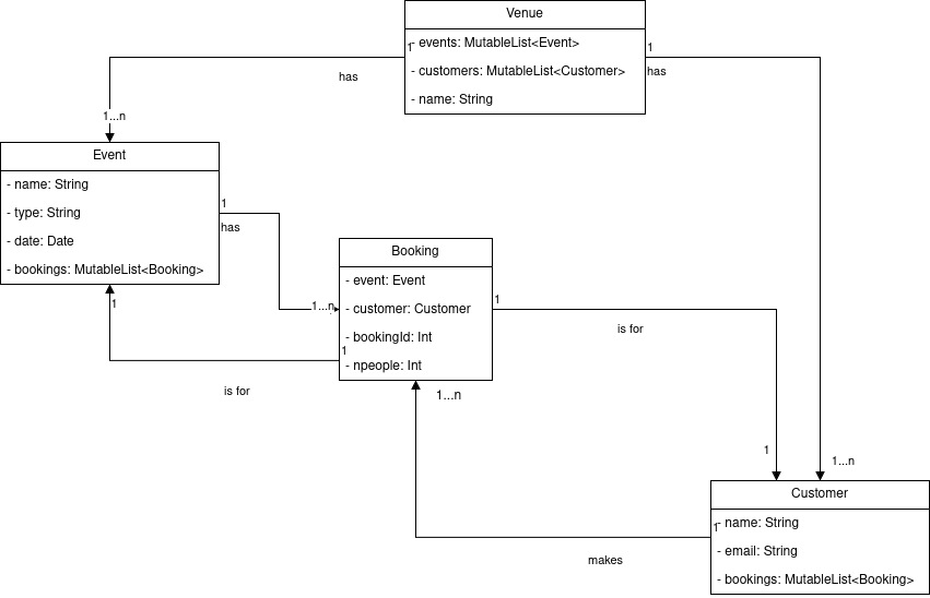
In terms of attributes, we first model the relationships as attributes.
- One
Venuecontains many events. SoVenuewould need to contain a list ofEvents. - One
Eventcontains many bookings. SoEventwould need to contain a list ofBookingss. - One
Bookingcontains one event. SoBookingwould need to contain anEventobject as an attribute. - One
Venuecontains many customers. SoVenuewould need to contain a list ofCustomers. - One
Customercontains many bookings. SoCustomerwould need to contain a list ofBookingss.
Others we could add, through analysing the scenario:
- a
Venuewould have a name (String); - an
Eventwould have a name (String) and a date (we'll use aDateobject for now), also a type e.g. music, comedy; - a
Customerwould have a name and probably an email given that the customers should be informed when an event is cancelled. - a
Bookingwould store the booking ID and number of people.
This gives us the class diagram below.
Exercise 5
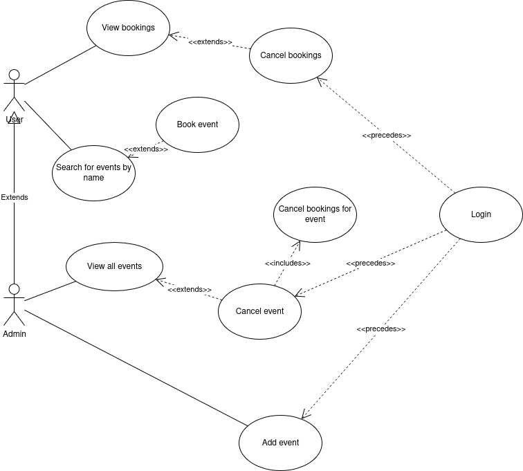
Answer to exercise 5
Use cases are tasks which users of the system should be able to perform. So, looking at the problem statement, these could include:
Regular user (customer):
- Search for events by name
- Book events
- View bookings
- Cancel bookings
Venue Staff:
All the above plus:
- View all events
- Add event
- Cancel events
- Cancel bookings for an event (include of Cancel events)
In terms of extends relationships we could have:
- Book events could extend from search by name
- Cancel bookings could extend from view bookings
- Cancel event could extend from view all events, or search for event
In terms of precedes relationships we could have:
- All the admin tasks would need to be preceded by login, and probably also all the customer tasks too as a user would need to login to book events and view/cancel their own bookings.
In terms of includes relationships we could have:
- Cancel bookings for an event would be included in cancel events
Exercise 6
Answer to exercise 6
Below is a use case diagram showing the above use cases.